
Back
Detailed below is the construction of The Triad, step by step. If you have any questions or comments, please dont hesitate to email me! Click on any image for a larger version.
 |
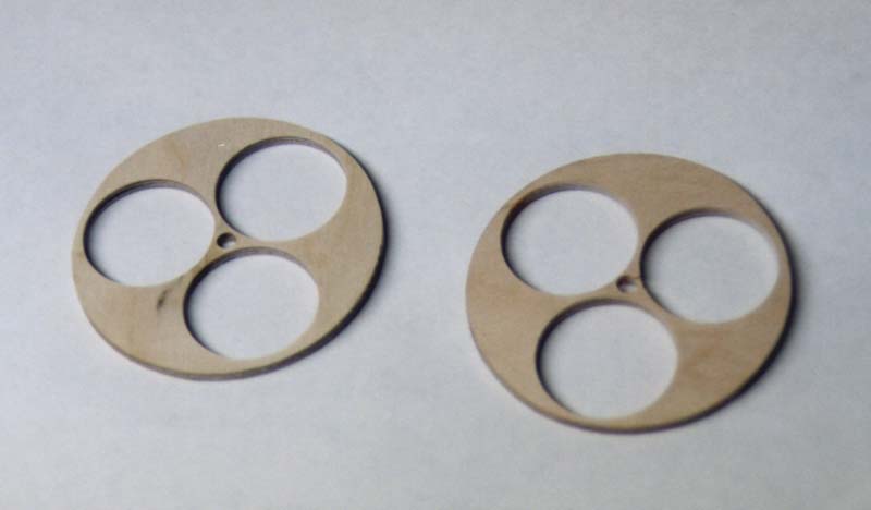
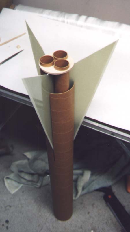
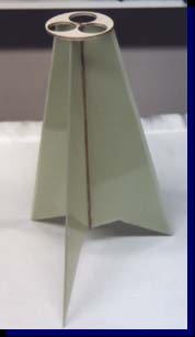
The entire rocket design was built around the 3x38mm motor mount configuration, the largest possible cluster I could fit in the 4" airframe. Imagine...3 J-570's in a 4" airframe! |
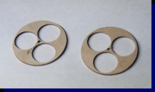
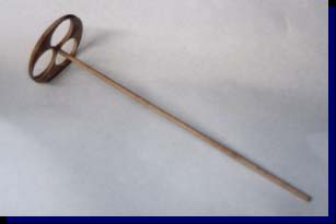
| Note the hole in the middle of the centering rings. The hole is a byproduct of the tools used to cut the centering rings. I took advantage of this, and used it to secure a hardwood spar in the center of the motor mount, providing a mounting surface for the fins and strengthening the motor mount structure. |
 |
 |
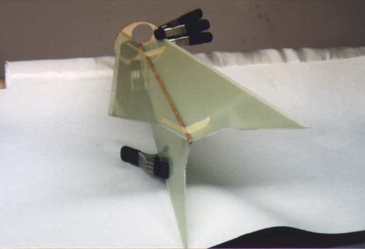
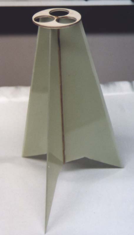
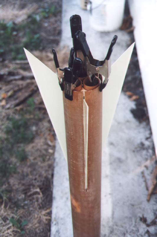
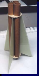
Here, the fins have been secured to the center spar. I attached each fin one at a time, held in place with clamps and masking tape until the resin cured. |
| Once the resin has cured, the initial motor mount structure was quite rigid. For all structural joints, I used TAP Plastics general purpose epoxy, a strong, medium viscosity resin with an approximate cure time of 2 hours. |
 |
 |
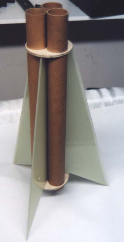
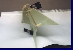
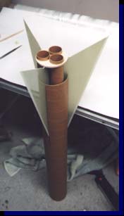
Once the motor tubes and the second centering ring were epoxied in place, the motor mount assembly was extremely strong. Almost ready to be glued into the airframe. |
| A quick dry-fit test ensures the fins are straight and everything fits smoothly into the pre-slotted phenolic airframe, once again from Giant Leap Rocketry. |
 |
 |
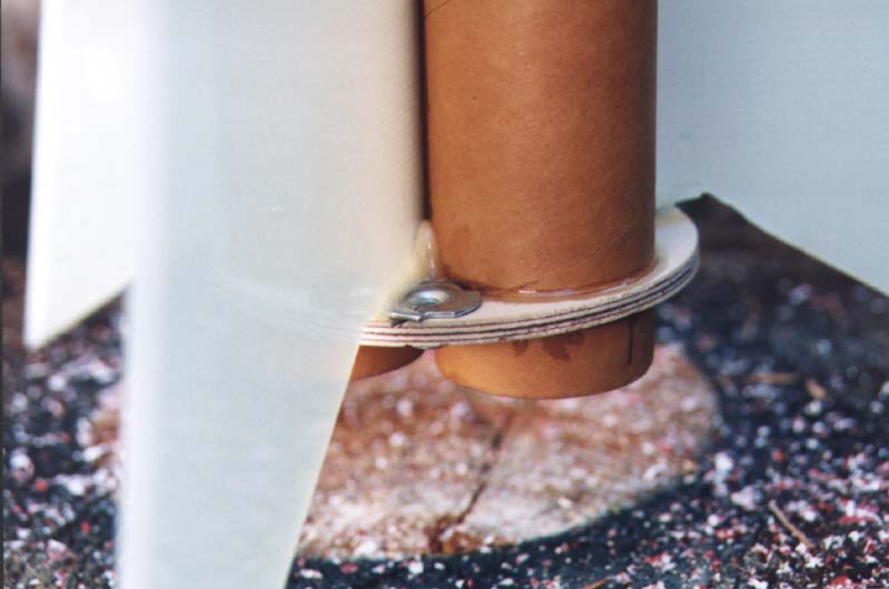
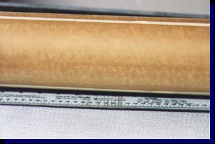
Here is a close-up view of the bottom end of the motor mount. Note the epoxy fillets around the motor tube, and the tight fit of the t-nut for positive motor retainment. Each motor tube has its own t-nut. |
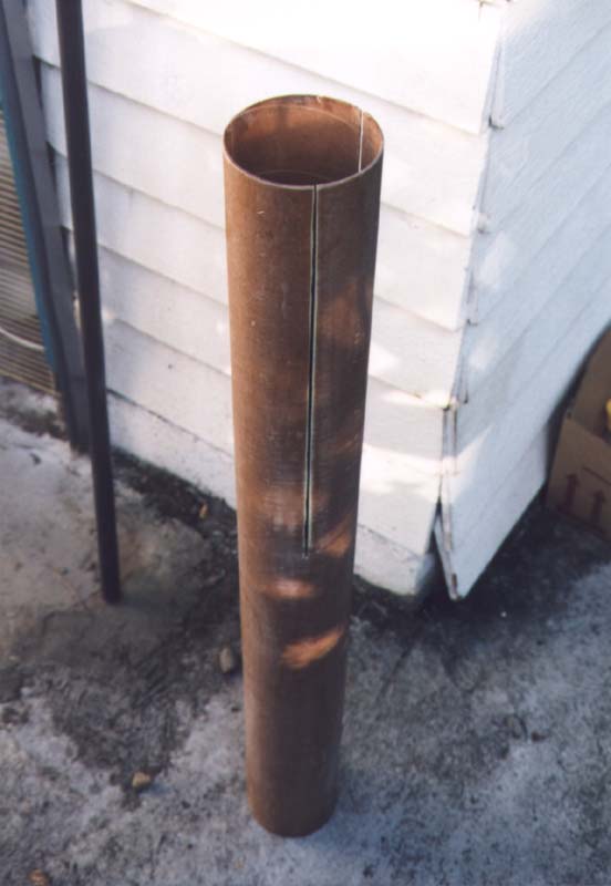
| Now that the motor mount assembly is complete, I begin to work on preparing the airframe. Since it was pre-slotted and I was planning on fiberglassing it, I needed to figure out a way to prevent the slots from getting fouled up with resin. I ended up covering each slot with masking tape, and then trimmed the tape so it was barely wider than the slots. Also note the airframe has been roughed-up to promote the adhesion of the fiberglass. |
 |
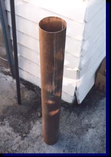 |
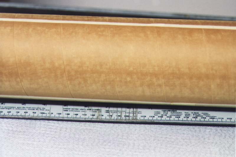
This is the airframe, after two layers of 3-oz satin-weave fiberglass. The tape over the slots worked perfectly, and it was easy to clear the fiberglass from the slots with a utility knife. |
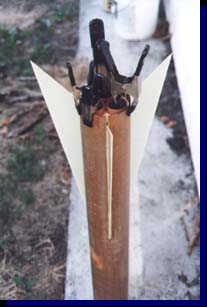
| Gluing the motor mount in place. Once all surfaces were rough-sanded and epoxy applied, I slid in the motor mount, and used clamps to keep everything together while the resin cured. |
 |
Coming soon - Pictures of the completed booster section, including anti-zipper setup. I'm currently borrowing the payload/altimiter section and nose cone from the Megaroc. Stay tuned for constuction of the altimiter bay for the Triad..
Back

Rocketry | Experimental | Webhosting | Email | Links | Home
Copyright 1998-2014 Greg Deputy - All Rights Reserved
|